RGB Binary Clock with Raspberry Pi Pico, DS3231, 74HC595 Shift Registers and TM1637 | MicroPython
Build an RGB binary clock on a Raspberry Pi Pico running MicroPython. Build an RGB binary clock on a Raspberry Pi Pico running MicroPython. Display hours, minutes and seconds simultaneously in RGB LED binary format using 74HC595 shift registers, a DS3231 hardware RTC for accurate offline timekeeping, and a TM1637 7-segment display for standard time. Written entirely in MicroPython with no external libraries required.
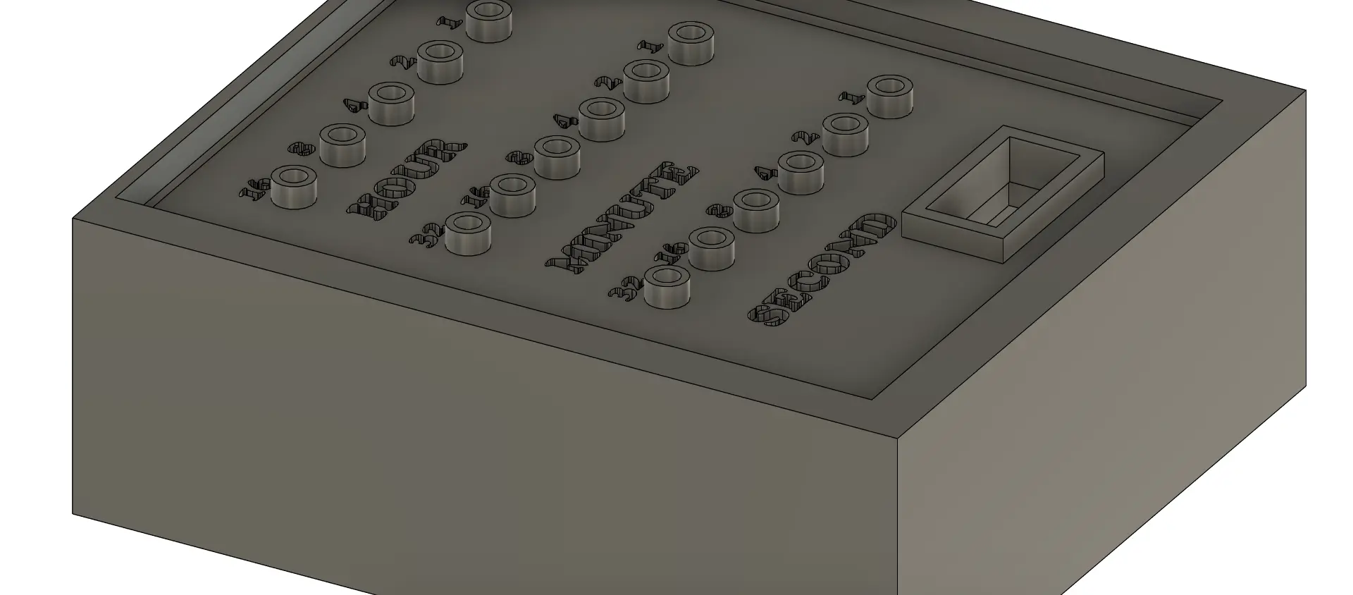
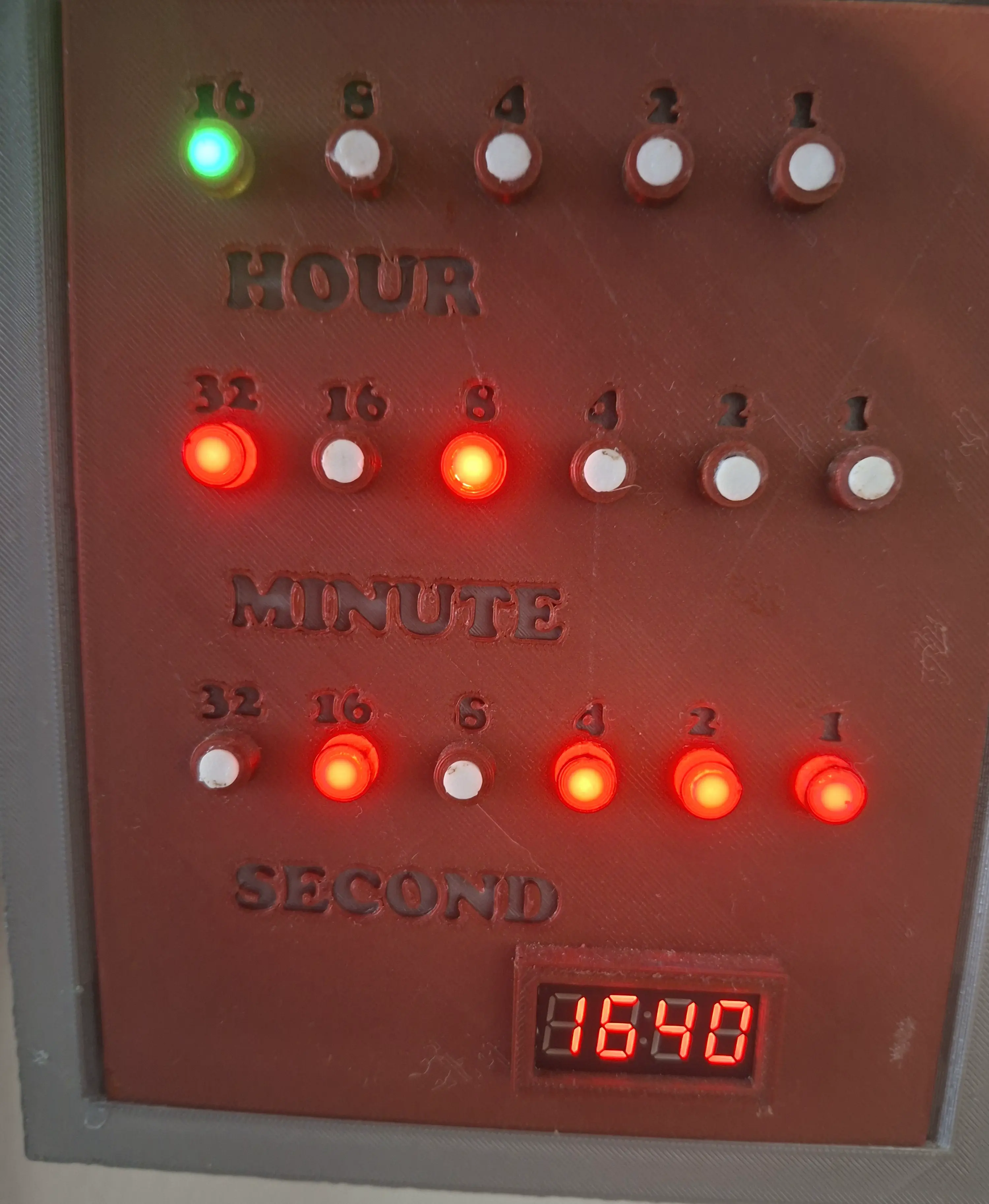
Project Photos
What You Need
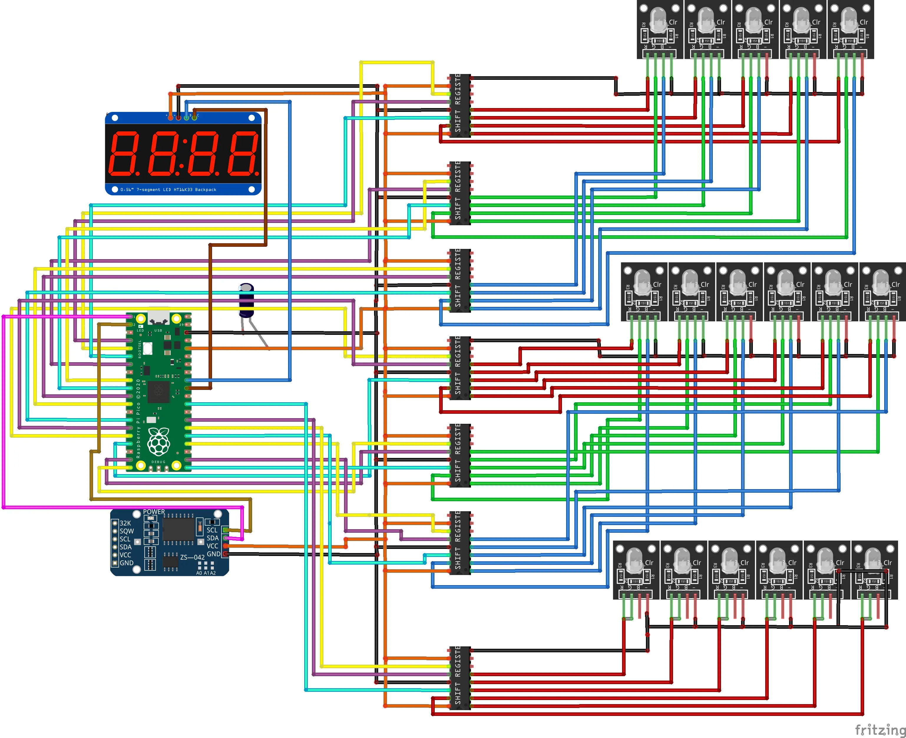
Wiring
DS3231 RTC (I2C)
| DS3231 Pin | GPIO |
|---|---|
| SDA | GPIO 0 |
| SCL | GPIO 1 |
| VCC | 3.3V |
| GND | GND |
TM1637 Display
| TM1637 Pin | GPIO |
|---|---|
| CLK | GPIO 26 |
| DIO | GPIO 27 |
| VCC | 3.3V |
| GND | GND |
Shift Register Pin Assignments
| Bank | Color | LATCH | CLOCK | DATA |
|---|---|---|---|---|
| Hours | Red | GPIO 2 | GPIO 3 | GPIO 4 |
| Hours | Green | GPIO 5 | GPIO 6 | GPIO 7 |
| Hours | Blue | GPIO 8 | GPIO 9 | GPIO 10 |
| Minutes | Red | GPIO 11 | GPIO 12 | GPIO 13 |
| Minutes | Green | GPIO 14 | GPIO 15 | GPIO 16 |
| Minutes | Blue | GPIO 17 | GPIO 18 | GPIO 19 |
| Seconds | Red only | GPIO 20 | GPIO 21 | GPIO 22 |
Note: The Fritzing diagram shows an HT16K33 backpack, a TM1637 is used in the actual build.
How It Works
The DS3231 RTC module provides accurate timekeeping via I2C and maintains time even during power loss. Once per second, the firmware reads the current hours, minutes, and seconds from the RTC and outputs the raw binary values to three separate LED banks via 74HC595 shift registers.
Hours and minutes are displayed using RGB LEDs. The active color channel rotates automatically hours rotate through red, green, and blue based on hour, and minutes rotate based on 20-minute intervals. Seconds are displayed using a dedicated red LED bank only. The TM1637 7-segment display shows the standard HHMM digital time simultaneously.
The RGB color rotation means the clock looks different depending on the time of day, which reinforces the binary reading habit, you must read the LEDs, not just glance at the color.
RGB Color Rotation Logic
| Hours (hour % 3) | Active Color |
|---|---|
| 0 (hours 0, 3, 6, 9, 12, 15, 18, 21) | Red |
| 1 (hours 1, 4, 7, 10, 13, 16, 19, 22) | Green |
| 2 (hours 2, 5, 8, 11, 14, 17, 20, 23) | Blue |
| Minutes (minute range) | Active Color |
|---|---|
| 0–19 | Red |
| 20–39 | Green |
| 40–59 | Blue |
How to Build It
Flash MicroPython firmware
Download the latest MicroPython firmware for your board from micropython.org and flash it using Thonny IDE or esptool. No external libraries are required beyond standard MicroPython.
Wire the components
Connect the DS3231 RTC and TM1637 display as shown in the wiring tables above. Then connect all 7 shift registers for the hours RGB, minutes RGB, and seconds red LED banks. Use an external power supply for the LEDs, do not power them from the MCU 3.3V pin.
Set the time
Before uploading, open main.py and update this line to your current local time:
rtc.datetime((2024, 8, 4, 1, 17, 36, 0))
# order: Year, Month, Date, Day, Hour, Minute, Second
The DS3231 will store the time and maintain it independently, so you only need to set it once.
Upload the code
Download the full source from GitHub and upload main.py to your device using Thonny IDE. Select the correct MicroPython interpreter and port before uploading.
Power on and read binary
On power-up all shift register outputs reset to zero. The clock then begins displaying time immediately. Hours and minutes appear in binary on the RGB LED banks, seconds on the red LED bank, and the TM1637 shows HHMM in standard format. Use the TM1637 to verify your binary reading is correct.
The Code
The full source is available on GitHub. The firmware includes a custom TM1637 driver, custom DS3231 driver, bitwise shift register control, and a precise 1Hz update loop. No external libraries required.
from machine import Pin, I2C
import utime

# TM1637 Library
class TM1637:
    TM1637_CMD1 = 0x40
    TM1637_CMD2 = 0xC0
    TM1637_CMD3 = 0x80
    TM1637_DSP_ON = 0x88
    TM1637_DELAY = 10

    _SEGMENTS = [0x3f, 0x06, 0x5b, 0x4f, 0x66, 0x6d, 0x7d, 0x07, 0x7f, 0x6f, 0x77, 0x7c, 0x39, 0x5e, 0x79, 0x71]

    def __init__(self, clk, dio):
        self.clk = clk
        self.dio = dio
        self.clk.init(Pin.OUT)
        self.dio.init(Pin.OUT)
        self._brightness = self.TM1637_DSP_ON | 7
        self.off()

    def _start(self):
        self.dio(0)
        utime.sleep_us(self.TM1637_DELAY)
        self.clk(0)
        utime.sleep_us(self.TM1637_DELAY)

    def _stop(self):
        self.clk(0)
        utime.sleep_us(self.TM1637_DELAY)
        self.dio(0)
        utime.sleep_us(self.TM1637_DELAY)
        self.clk(1)
        utime.sleep_us(self.TM1637_DELAY)
        self.dio(1)

    def _write_data(self, data):
        for bit in range(8):
            self.dio((data >> bit) & 1)
            self.clk(1)
            utime.sleep_us(self.TM1637_DELAY)
            self.clk(0)
            utime.sleep_us(self.TM1637_DELAY)
        self.clk(1)
        utime.sleep_us(self.TM1637_DELAY)
        self.clk(0)
        utime.sleep_us(self.TM1637_DELAY)

    def _write_cmd(self, cmd):
        self._start()
        self._write_data(cmd)
        self._stop()

    def on(self):
        self._write_cmd(self._brightness)

    def off(self):
        self._write_cmd(self.TM1637_DSP_ON)

    def brightness(self, val=None):
        if val is None:
            return self._brightness & 0x07
        self._brightness = self.TM1637_DSP_ON | (val & 0x07)
        self.on()

    def write(self, segments, pos=0):
        self._write_cmd(self.TM1637_CMD1)
        self._start()
        self._write_data(self.TM1637_CMD2 | pos)
        for seg in segments:
            self._write_data(seg)
        self._stop()
        self.on()

    def encode_digit(self, digit):
        return self._SEGMENTS[digit & 0x0f]

    def encode_string(self, string):
        segments = []
        for char in string:
            if char == ' ':
                segments.append(0x00)
            elif '0' <= char <= '9':
                segments.append(self._SEGMENTS[ord(char) - ord('0')])
            else:
                segments.append(0x00)
        return segments


# DS3231 RTC Library
class DS3231:
    DS3231_I2C_ADDR = 0x68

    def __init__(self, i2c):
        self.i2c = i2c

    def _bcd2bin(self, value):
        return (value & 0x0F) + ((value >> 4) * 10)

    def _bin2bcd(self, value):
        return (value // 10 << 4) + (value % 10)

    def datetime(self, dt=None):
        if dt is None:
            data = self.i2c.readfrom_mem(self.DS3231_I2C_ADDR, 0x00, 7)
            return (self._bcd2bin(data[0]), self._bcd2bin(data[1]), self._bcd2bin(data[2]),
                    self._bcd2bin(data[3]), self._bcd2bin(data[4]), self._bcd2bin(data[5]), self._bcd2bin(data[6]))
        else:
            data = bytearray(7)
            data[0] = self._bin2bcd(dt[6])  # Seconds
            data[1] = self._bin2bcd(dt[5])  # Minutes
            data[2] = self._bin2bcd(dt[4])  # Hours
            data[3] = self._bin2bcd(dt[3])  # Day
            data[4] = self._bin2bcd(dt[2])  # Date
            data[5] = self._bin2bcd(dt[1])  # Month
            data[6] = self._bin2bcd(dt[0])  # Year
            self.i2c.writeto_mem(self.DS3231_I2C_ADDR, 0x00, data)


# I2C and peripherals
i2c = I2C(0, scl=Pin(1), sda=Pin(0))
rtc = DS3231(i2c)
tm = TM1637(clk=Pin(26), dio=Pin(27))

# Set RTC time: (Year, Month, Date, Day, Hour, Minute, Second)
rtc.datetime((2024, 8, 4, 1, 17, 36, 0))

# Shift register pins  Hours RGB
LATCH_PIN_HOUR_RED   = Pin(2,  Pin.OUT)
CLOCK_PIN_HOUR_RED   = Pin(3,  Pin.OUT)
DATA_PIN_HOUR_RED    = Pin(4,  Pin.OUT)
LATCH_PIN_HOUR_GREEN = Pin(5,  Pin.OUT)
CLOCK_PIN_HOUR_GREEN = Pin(6,  Pin.OUT)
DATA_PIN_HOUR_GREEN  = Pin(7,  Pin.OUT)
LATCH_PIN_HOUR_BLUE  = Pin(8,  Pin.OUT)
CLOCK_PIN_HOUR_BLUE  = Pin(9,  Pin.OUT)
DATA_PIN_HOUR_BLUE   = Pin(10, Pin.OUT)

# Shift register pins  Minutes RGB
LATCH_PIN_MINUTES_RED   = Pin(11, Pin.OUT)
CLOCK_PIN_MINUTES_RED   = Pin(12, Pin.OUT)
DATA_PIN_MINUTES_RED    = Pin(13, Pin.OUT)
LATCH_PIN_MINUTES_GREEN = Pin(14, Pin.OUT)
CLOCK_PIN_MINUTES_GREEN = Pin(15, Pin.OUT)
DATA_PIN_MINUTES_GREEN  = Pin(16, Pin.OUT)
LATCH_PIN_MINUTES_BLUE  = Pin(17, Pin.OUT)
CLOCK_PIN_MINUTES_BLUE  = Pin(18, Pin.OUT)
DATA_PIN_MINUTES_BLUE   = Pin(19, Pin.OUT)

# Shift register pins  Seconds red only
LATCH_PIN_SECONDS_RED = Pin(20, Pin.OUT)
CLOCK_PIN_SECONDS_RED = Pin(21, Pin.OUT)
DATA_PIN_SECONDS_RED  = Pin(22, Pin.OUT)

def update_shift_register(latch_pin, clock_pin, data_pin, value):
    latch_pin.value(0)
    for i in range(8):
        clock_pin.value(0)
        data_pin.value((value >> (7 - i)) & 1)
        clock_pin.value(1)
    latch_pin.value(1)

def reset_leds(latch_pins, clock_pins, data_pins):
    for latch_pin, clock_pin, data_pin in zip(latch_pins, clock_pins, data_pins):
        update_shift_register(latch_pin, clock_pin, data_pin, 0)

def display_time(seconds_latch, seconds_clock, seconds_data,
                 minutes_latch_pins, minutes_clock_pins, minutes_data_pins,
                 hours_latch_pins, hours_clock_pins, hours_data_pins):

    last_hour_color_index = -1
    last_minute_color_index = -1

    while True:
        start_time = utime.ticks_ms()

        try:
            now = rtc.datetime()
            seconds, minutes, hours = now[0], now[1], now[2]
        except Exception as e:
            print(f"Error reading RTC: {e}")
            continue

        hours_color_index   = hours % 3
        minutes_color_index = (minutes // 20) % 3

        if hours_color_index != last_hour_color_index:
            reset_leds(hours_latch_pins, hours_clock_pins, hours_data_pins)
            last_hour_color_index = hours_color_index

        if minutes_color_index != last_minute_color_index:
            reset_leds(minutes_latch_pins, minutes_clock_pins, minutes_data_pins)
            last_minute_color_index = minutes_color_index

        update_shift_register(seconds_latch, seconds_clock, seconds_data, seconds)
        update_shift_register(minutes_latch_pins[minutes_color_index], minutes_clock_pins[minutes_color_index], minutes_data_pins[minutes_color_index], minutes)
        update_shift_register(hours_latch_pins[hours_color_index], hours_clock_pins[hours_color_index], hours_data_pins[hours_color_index], hours)

        tm.write(tm.encode_string(f"{hours:02d}{minutes:02d}"))

        while utime.ticks_diff(utime.ticks_ms(), start_time) < 1000:
            pass


def main():
    reset_leds(
        [LATCH_PIN_HOUR_RED, LATCH_PIN_HOUR_GREEN, LATCH_PIN_HOUR_BLUE],
        [CLOCK_PIN_HOUR_RED, CLOCK_PIN_HOUR_GREEN, CLOCK_PIN_HOUR_BLUE],
        [DATA_PIN_HOUR_RED,  DATA_PIN_HOUR_GREEN,  DATA_PIN_HOUR_BLUE]
    )
    reset_leds(
        [LATCH_PIN_MINUTES_RED, LATCH_PIN_MINUTES_GREEN, LATCH_PIN_MINUTES_BLUE],
        [CLOCK_PIN_MINUTES_RED, CLOCK_PIN_MINUTES_GREEN, CLOCK_PIN_MINUTES_BLUE],
        [DATA_PIN_MINUTES_RED,  DATA_PIN_MINUTES_GREEN,  DATA_PIN_MINUTES_BLUE]
    )
    reset_leds([LATCH_PIN_SECONDS_RED], [CLOCK_PIN_SECONDS_RED], [DATA_PIN_SECONDS_RED])

    display_time(
        LATCH_PIN_SECONDS_RED, CLOCK_PIN_SECONDS_RED, DATA_PIN_SECONDS_RED,
        [LATCH_PIN_MINUTES_RED, LATCH_PIN_MINUTES_GREEN, LATCH_PIN_MINUTES_BLUE],
        [CLOCK_PIN_MINUTES_RED, CLOCK_PIN_MINUTES_GREEN, CLOCK_PIN_MINUTES_BLUE],
        [DATA_PIN_MINUTES_RED,  DATA_PIN_MINUTES_GREEN,  DATA_PIN_MINUTES_BLUE],
        [LATCH_PIN_HOUR_RED,  LATCH_PIN_HOUR_GREEN,  LATCH_PIN_HOUR_BLUE],
        [CLOCK_PIN_HOUR_RED,  CLOCK_PIN_HOUR_GREEN,  CLOCK_PIN_HOUR_BLUE],
        [DATA_PIN_HOUR_RED,   DATA_PIN_HOUR_GREEN,   DATA_PIN_HOUR_BLUE]
    )

main()
Want to learn the fundamentals first?
The free Introduction to Arduino course on DevSTEM covers everything you need before tackling projects like this.
Start the Course